
PRODUCTS
Center
WHG Series – Heavy-Duty Ball Linear Guides
The WGH Series linear guides are four-row, single-arc-tooth-profile linear guides that integrate an optimized structural design to create precision linear guides capable of handling ultra-heavy loads. Compared to other linear guides, they offer enhanced load-carrying capacity and rigidity. Featuring equal load distribution in all four directions and self-aligning capabilities, they compensate for mounting surface errors to meet high-precision requirements. The concepts of high speed, high load capacity, high rigidity, and high precision have become the global trend in the development of industrial products. WISSNER’s four-row ultra-heavy-duty linear guides are products developed based on this philosophy.
Features of the WGH Series Linear Guides
(1) Self-aligning Capability
The DF (45°-45°) combination derived from arc-shaped grooves ensures that during installation, the elastic deformation of the steel balls and the shifting of contact points allow the linear guide block to internally compensate for minor deviations in the mounting surface. This self-aligning capability results in high-precision, stable, and smooth motion.
(2) Interchangeability
Due to strict control over manufacturing precision, the dimensions of the linear guides are maintained within a consistent range. Additionally, the sliders feature a retainer design to prevent ball loss. As a result, certain series offer precision interchangeability, allowing customers to order either the guide or the slider as needed, or to store them separately to reduce storage space.
(3) High Rigidity in All Directions
The use of four-row arc-shaped grooves, combined with a 45-degree contact angle of the four rows of steel balls, creates an ideal two-point contact configuration that can withstand loads from both vertical and horizontal directions; preload can also be applied when necessary to further enhance rigidity.
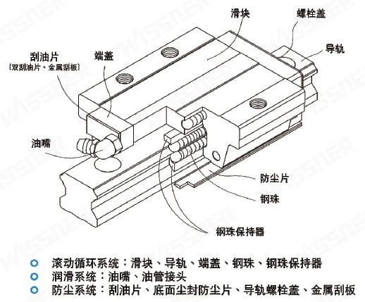
Product Specifications
The WGH series is divided into two types of linear guides: non-interchangeable and interchangeable. Both share the same specifications and dimensions; the main difference is that the sliders and rails of the interchangeable type can be used individually, offering greater convenience. However, their assembly accuracy cannot match the ultra-high precision of the non-interchangeable type. Nevertheless, due to WISSNER’s excellent dimensional control and strict quality standards during manufacturing, the assembly accuracy of the interchangeable type has now reached a certain level, making them an excellent choice for customers who do not require matched linear guide installations. The product specifications and model numbers for linear guides primarily indicate the dimensions, type, accuracy grade, preload, and other technical requirements to facilitate mutual confirmation of the product during the ordering process.
WGH Series Types
(1) Slider Types
WISSNER offers two types of linear guides: flange-type and square-type. Square-type linear guides are divided into H-type and L-type; the L-type is a low-profile version of the H-type, with an assembly height identical to that of the flange-type linear guide.
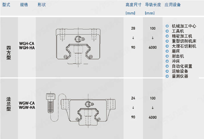
(2) Guide Type
WISSNER offers lock-type screw-hole guides for easy installation and use by customers.

Accuracy Grades
The WGH series linear guides are available in five accuracy grades: Standard, High, Precision, Ultra-Precision, and Ultra-High Precision. Customers can select the appropriate grade based on their equipment’s accuracy requirements.
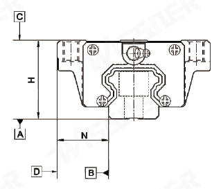
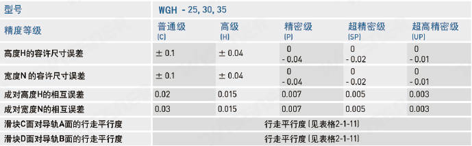
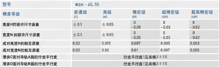
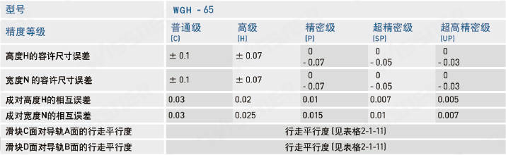
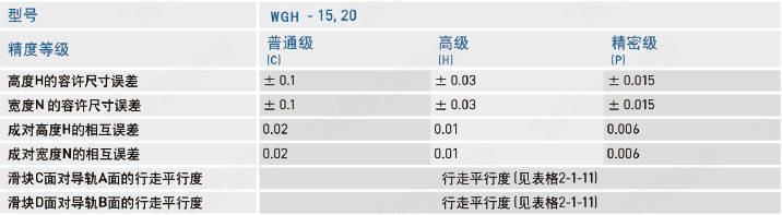
(1) Non-Interchangeable Linear Guide Accuracy
Assembly Accuracy Table (in mm)
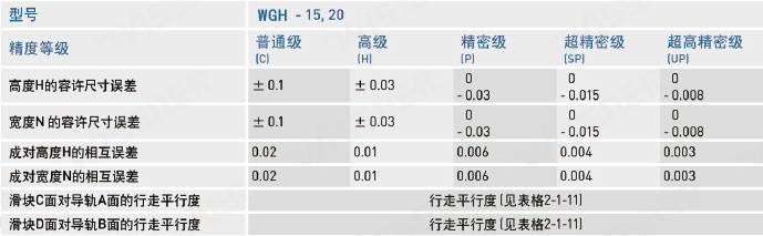
Assembly Accuracy Table (in mm)
Assembly Accuracy Table (in mm)
Assembly Accuracy Table (in mm)
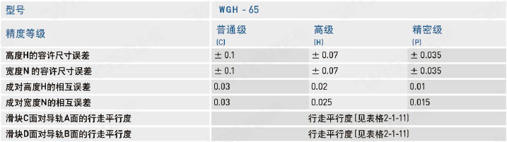
(2) Interchangeable Linear Guide Precision
Individual Part Precision Table (in mm)
Precision Table for Individual Components (in mm)
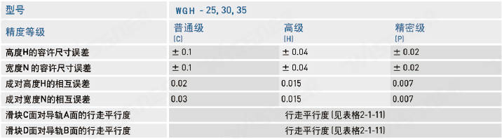
Precision Table for Individual Components (in mm)
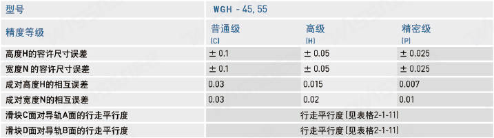
Single-Part Precision Table (in mm)
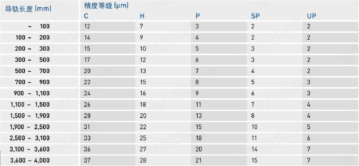
(3) Travel Parallelism Precision
Preload
(1) Definition of Preload
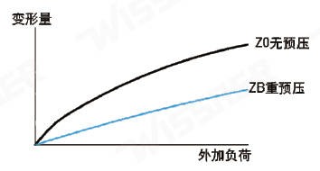
Preload is a load applied to the balls in advance; specifically, it involves increasing the ball diameter to create preload by utilizing the negative clearance between the balls and the raceway. This enhances the rigidity of the linear guide and eliminates backlash; As illustrated in the figure on the right, increasing the preload enhances the rigidity of the linear guide. However, for smaller sizes, it is recommended to select a preload level of “light preload” or lower to avoid reducing service life due to excessive preload.
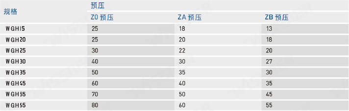
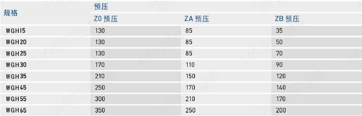
(2) Preload Levels
The WHG series linear guides offer three standard preload levels, allowing you to select the appropriate preload based on the application.
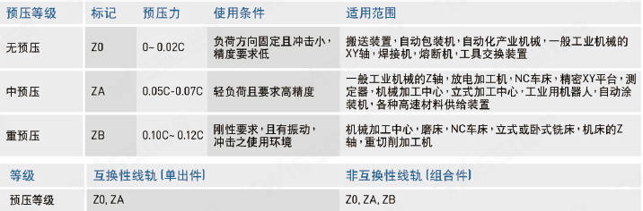
Note: Load C represents the dynamic rated load
Lubrication Methods
(1) Lubricating Grease
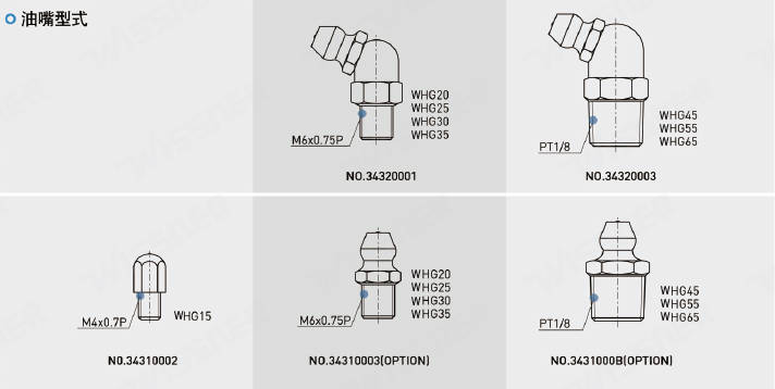
Grease Fitting Types
Grease Fitting Location
Depending on customer requirements, grease fittings can be installed at the front or rear end of the slide for automatic lubrication. The WHG series specifically provides a side grease port on the end cap for installing grease fittings (typically straight grease fittings), enabling lateral lubrication. It is recommended to position the lateral lubrication point on the non-reference side; however, it may also be placed on the reference side if special requirements exist. Please contact us if you have the above-mentioned lateral lubrication requirements. For linear guides that use piping for automatic grease supply, select the appropriate grease fitting based on the type of connecting pipe.
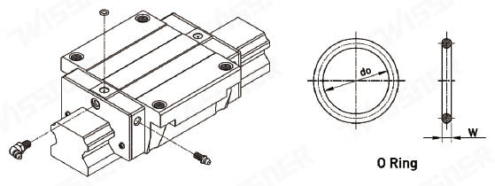
O-Ring Specifications and Maximum Permissible Drilling Depth

Grease Filling Volume per Slider

Lubrication Frequency
Check the grease every 100 km or every 3–6 months.
Grease Supply Rate

Dust Protection Features
(1) Standard Dust Protection Code
For use in general operating environments with no special requirements. If any of the following dust protection accessories are needed, please add the corresponding code after the product model number.
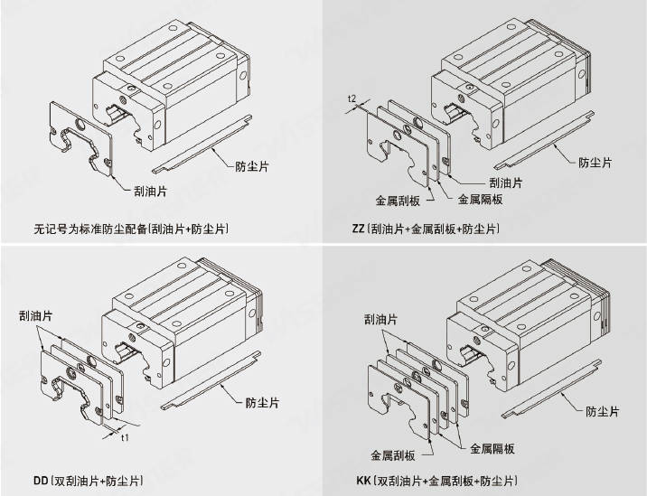
Note: WGH20/25 models feature a non-metallic partition design.
Friction Force
This resistance value represents the maximum resistance of a single oil scraper blade.
WGH Series Oil Scraper Resistance

Note: 1 kgf = 9.81 N
Mounting Surface Error
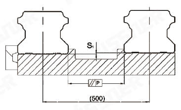
The WGH series features arc-shaped two-point contact linear guides; their self-aligning characteristics allow them to accommodate minor mounting surface errors without affecting the smoothness of linear motion; The table below lists the allowable errors for the mounting surface:
Allowable Flatness Error (P) Unit (µm)
Permissible Vertical Leveling Error (S1) Unit (µm)
Note: Permissible values are proportional to the distance between the shafts
(1) Mounting Surface Shoulder Height and Chamfer
When installing linear guides, it is essential to ensure the mounting surface shoulder is properly prepared. If the chamfer is too large, the protruding areas can compromise the linear guide’s accuracy, while excessive height may interfere with the slide block. Therefore, adhering to the recommended specifications for the mounting surface shoulder will eliminate installation accuracy issues.
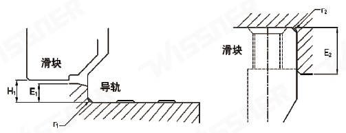
Shoulder flatness and chamfer
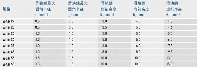
(2) Torque values for guide rail mounting screws
Whether the guide rails are securely tightened and flush with the reference surface during installation has a significant impact on the accuracy of the linear guide rails. Therefore, to ensure that every screw is properly tightened, it is recommended to use the following torque values when tightening the assembly screws.
Torque Values
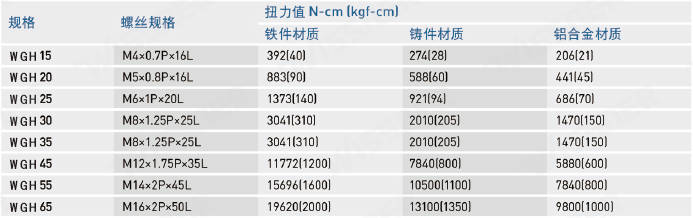
Standard and Maximum Lengths for Single Linear Guides
WISSNER maintains a stock of standard-length linear guides to meet customer needs. When ordering non-standard-length guides, the end face distance E should preferably not exceed 1/2P to prevent instability at the ends after assembly—which could reduce the linear guide’s precision—due to an excessively large E dimension.
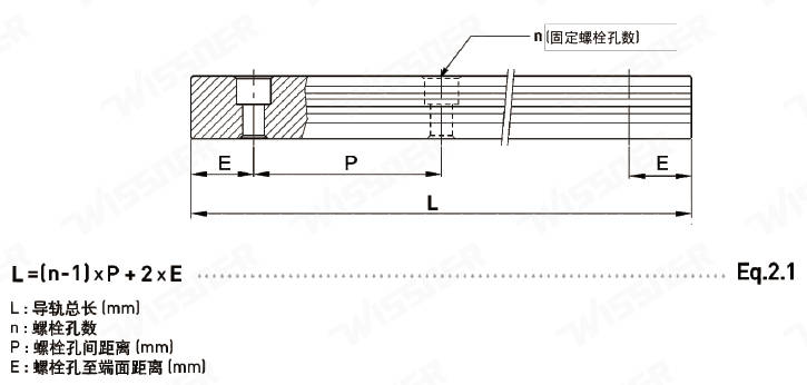
Guide Rail Length
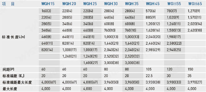
Note: 1. The typical tolerance for the E dimension of standard guide rails is 0.5 to -0.5 mm; the tolerance for the E dimension at the threaded connection ends is stricter, ranging from 0 to -0.3 mm.
2. The maximum standard end-to-end length refers to the maximum length of a guide rail where both the left and right end distances are standard end distances.
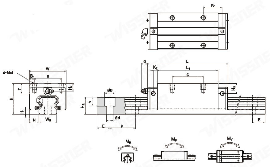
WGH Series Linear Guide Dimension Table
(1) WGH-CA/WGH-HA
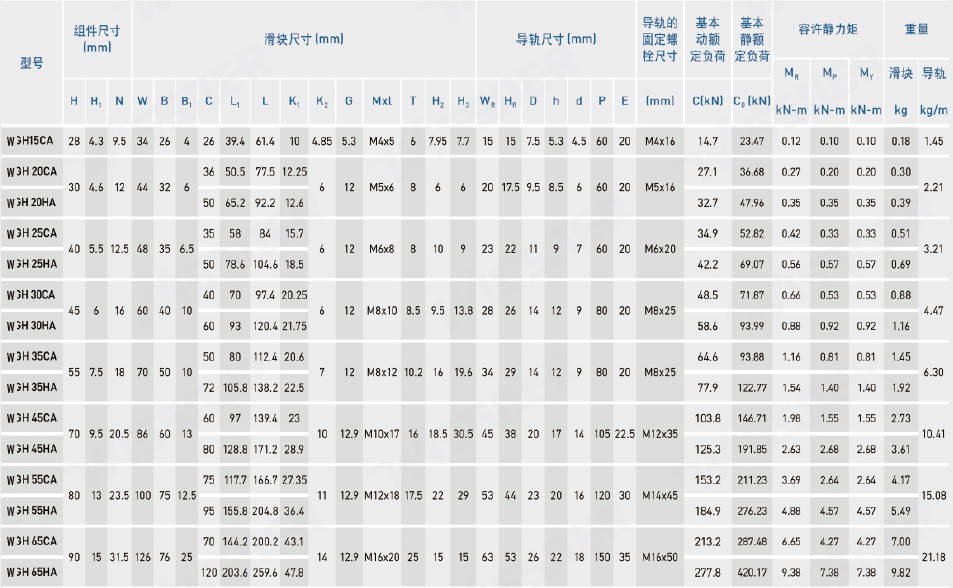
Note: 1 kgf = 9.81 N
(2) WEG-CA/WGW-HA
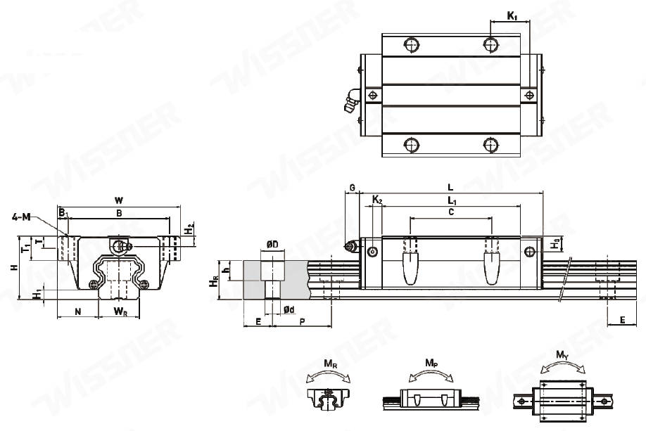
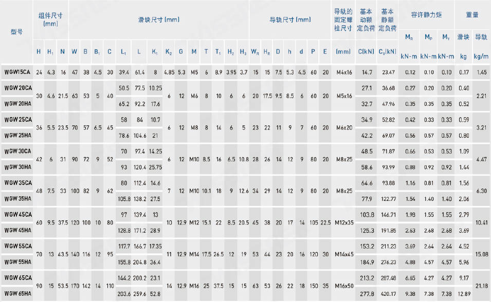
Note: 1 kgf = 9.81 N