
技術資料
TECHNICAL DATA
- Advantages and Features of WISSNER Linear Guides
- Selection Criteria
- Rated Load
- Service Life of Linear Guides
Service Life of Linear Guides
Service Life
When a linear guide is subjected to a load and in motion, the ballway surface and the steel balls are continuously subjected to cyclic stress. Once the critical value for rolling fatigue is reached, fatigue damage begins to occur at the contact surfaces, and fish-scale-like flakes start to peel off from parts of the surface. This phenomenon is called surface spalling. Service life is defined as the total operating distance until surface spalling occurs on the raceway surface and balls due to material fatigue.
1-4-2 Rated Service Life
The service life of linear guides exhibits significant variability; even products from the same manufacturing batch, when used under identical operating conditions, will have differing service lives; This is largely attributed to inherent variations in the fatigue characteristics of the material itself. Therefore, to define the service life of a linear guide, the rated service life is generally used as the benchmark; it is defined as: the total operating distance that 90% of a batch of identical products can achieve when operated individually under the same conditions and at the rated load without experiencing surface spalling.
Service Life Calculation
The service life of a linear guide varies depending on the actual working load it bears; the service life can be estimated based on the basic dynamic rated load and working load of the selected linear guide.
(1) Without considering the influence of environmental factors, the service life calculation is as follows.
L: Rated life
C: Basic dynamic rated load
P: Operating load
(2) When environmental factors affecting the use of linear guides are taken into account, their service life will vary depending on the motion conditions, the surface hardness of the raceway, and the system temperature.
L: Service life
fh: Hardness factor
C: Basic dynamic rated load
ft: Temperature factor
PC: Operating load
fW : Load factor
Service life factor
(1) Hardness factor ( fh )
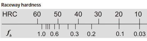
The hardness of the contact surfaces on the ball tracks of linear guides must be between HRC 58 and 62 at a specified hardening depth. If the hardness value does not meet the required level, the rated load and service life of the linear guide will be reduced. In this case, the dynamic and static rated loads are calculated by multiplying the values listed in the dimension table by the corresponding hardness coefficient. All linear guides manufactured by WISSNER meet a hardness requirement of HRC 58 or higher; therefore, fh is 1.
(2) Temperature Coefficient ( ft )
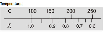
System temperature affects the material of the linear guide. When the temperature exceeds 100°C, the rated load and service life of the linear guide will decrease. In this case, the dynamic and static rated loads are calculated by multiplying the values listed in the dimension table by the corresponding temperature coefficient. Since some components are made of plastic and are less resistant to high temperatures, it is recommended that the operating temperature remain below 100°C.
(3) Load Factor (fw )
In addition to the linear guide’s own weight, inertial loads during startup and stopping, and torque loads caused by suspension, the loads acting on the linear guide also include vibration and shock loads associated with motion. These types of loads are not easy to calculate. Based on experience and depending on the load conditions and operating speed, it is recommended to multiply the calculated load value by the corresponding load factor.
Table 2: Load Factors
| Load Conditions | Operating Speed | fw |
|---|---|---|
| No impact forces and smooth operation | V ≤ 15 m/min | 1 ~ 1.2 |
| Minimal impact force | 15 m/min < V ≤ 60 m/min | 1.2 ~ 1.5 |
| Normal load | 60 m/min < V ≤ 120 m/min | 1.2 ~ 1.5 |
| Subject to impact and vibration | V > 120 m/min | 2.0 ~ 3.5 |
Conversion of Service Life to Time
Convert the service life distance to service life time based on operating speed and frequency.
Lh : Service life (hr)
L : Service life (km)
Ve : Operating speed (m/min)
C/P : Load ratio